What is a vernier caliper? How to use?

Instructions on use


  • The Vernier caliper is an extremely precise measuring instrument; the reading error is 1/20 mm = 0.05 mm.
  • Close the jaws lightly on the object to be measured.
  • If you are measuring something with a round cross section, make sure that the axis of the object is perpendicular to the caliper. This is necessary to ensure that you are measuring the full diameter and not merely a chord.
  • Ignore the top scale, which is calibrated in inches.
  • Use the bottom scale, which is in metric units.
  • Notice that there is a fixed scale and a sliding scale.
  • The boldface numbers on the fixed scale are centimeters.
  • The tick marks on the fixed scale between the boldface numbers are millimeters.
  • There are ten tick marks on the sliding scale. The left-most tick mark on the sliding scale will let you read from the fixed scale the number of whole millimeters that the jaws are opened.
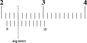
    Example 1
  • In the example above, the leftmost tick mark on the sliding scale is between 21 mm and 22 mm, so the number of whole millimeters is 21.
  • Next we find the tenths of millimeters. Notice that the ten tick marks on the sliding scale are the same width as nine ticks marks on the fixed scale. This means that at most one of the tick marks on the sliding scale will align with a tick mark on the fixed scale; the others will miss.
  • The number of the aligned tick mark on the sliding scale tells you the number of tenths of millimeters. In the example above, the 3rd tick mark on the sliding scale is in coincidence with the one above it, so the caliper reading is (21.30 ± 0.05) mm.
  • If two adjacent tick marks on the sliding scale look equally aligned with their counterparts on the fixed scale, then the reading is half way between the two marks. In the example above, if the 3rd and 4th tick marks on the sliding scale looked to be equally aligned, then the reading would be (21.35 ± 0.05) mm.
  • On those rare occasions when the reading just happens to be a "nice" number like 2 cm, don't forget to include the zero decimal places showing the precision of the measurement and the reading error. So not 2 cm, but rather (2.000 ± 0.005) cm or (20.00 ± 0.05) mm.

Comments

Popular posts from this blog

Dial Indicator | Dial Gauge | Types Of Dial Indicators | Working Principle

The Dial indicator is a mechanical mean, having gears and pinions or levers for magnification system. They can responses to linear measurement  even when they are too small. The Dial Indicators can be used as Comparotors Basically, comparators are the precession measuring instruments used to compare the workpiece measurements with the standard measurements. When this Dial Indicator is used in any measuring equipment for comparison purpose then these equipment are called  Dial Gauges. A Dial Indicator must be mounted on any other base/Equipment, otherwise, it will be useless.  The accuracy of the dial indicator is up to 0.001 mm are available. Construction of Dial Indicators There is a classification of dial indicators based on their dial shape. They are sector shape Dial Indicator and Circular shape Dial Indicator. But sector type is a quite limited range, so this sector type Dial Indicator is used for extremely accurate measurements. The circular type of Dial Indicat

Gear Basics

What is a gear ? A gear is a kind of machine element in which teeth are cut around cylindrical or cone shaped surfaces with equal spacing. By meshing a pair of these elements, they are used to transmit rotations and forces from the driving shaft to the driven shaft. Gears can be classified by shape as involute, cycloidal and trochoidal gears. Also, they can be classified by shaft positions as parallel shaft gears, intersecting shaft gears, and non-parallel and non-intersecting shaft gears. The history of gears is old and the use of gears already appears in ancient Greece in B.C. in the writing of Archimedes. A sample box of various types of gears Types of Gears Various types of gears There are many types of gears such as spur gears, helical gears, bevel gears, worm gears, gear rack, etc. These can be broadly classified by looking at the positions of axes such as parallel shafts, intersecting shafts and non-intersecting shafts. It is necessary to accurately understand th

RRB JE METROLOGY FULL DETAIL SYLLABUS EXPLANATION

What is the linear measurement and Types of linear measuring instruments. There are a wide variety of geometries that are measured in angular units. These varieties include angular separation of bounding planes, digression from a basic direction, angular spacing conditions related to a circle, etc. Because of these diverse geometrical forms, different types of methods, equipment and instruments are available to measure angles in common angular units of degree, minute and second. Several factors come into the role in the selection of appropriate angular measuring instrument. These factors may be the size, general shape of the part, the location and angular accessibility of the feature to be measured, expected a range of accuracy, etc. As in linear measurement, they can be categorized into two groups. The first one is standard line instrument. It includes divided scales like protractors, Bevel Protractors. The second category of angular measuring instruments is called face stan