What is the linear measurement and Types of linear measuring instruments.
There are a wide variety of geometries that are measured in angular units. These varieties include angular separation of bounding planes, digression from a basic direction, angular spacing conditions related to a circle, etc. Because of these diverse geometrical forms, different types of methods, equipment and instruments are available to measure angles in common angular units of degree, minute and second.
Several factors come into the role in the selection of appropriate angular measuring instrument. These factors may be the size, general shape of the part, the location and angular accessibility of the feature to be measured, expected a range of accuracy, etc.
As in linear measurement, they can be categorized into two groups. The first one is standard line instrument. It includes divided scales like protractors, Bevel Protractors. The second category of angular measuring instruments is called face standard instruments. Sine bars and angle gauges fall in this group.
Protractors:
The protractor is the simplest instrument for measuring angles between two faces. It consists of two arms and an engraved circular scale. The two arms can be set along the faces between which the angle is to be measured. The body of the instrument is extended to form one of the arms. A simple protractor consists of a blade that pivots about a semicircular head that is graduated in angular units (e.g., degrees, radians). To use, the blade is rotated to a position corresponding to some part angle to be measured and the angle is read off the angular scale.

Bevel Protractor:
Bevel Protractor is an angular measuring instrument capable of measuring angles to within 5 min. Bevel Protractor consists of a base to which a vernier scale is fixed. A protractor dial is mounted on the circular section of the base. The protractor dial is marked in degrees with every tenth degree numbered. The sliding blade is fitted into the dial; it may be extended to either sides and set at any angle to the base. The blade and the dial are rotated together as a unit. Fine adjustment is obtained with a small knurled headed pinion that, when turned, engages with a gear attached to the blade mount. The protractor dial may be locked in any position using the dial clamp nut.
Measurement in a bevel protractor instrument is made either by embracing the two bounding elements of the angle or by extraneous referencing. The vernier protractor is used to measure an angle greater than 90° but less than 180°. An acute angle attachment is fastened to the vernier protractor to measure angles less than 90°. The main scale is divided into two arcs of 180°. Each arc is divided into two quadrants of 90° and has graduation from 0° to 90° to the left and right of the zero line, with every tenth degree numbered. The vernier scale is divided into 12 spaces on each side of its zero (total 24). The spacing in the vernier scale is made in such a way that least count of it corresponds to 1 /12th of a degree, which is equal to 5′.
If the zero on the vernier scale coincides with a line on the main scale, the number of vernier graduations beyond the zero need to be multiplied by 5 and added to the number of full degrees indicated on the vernier protractor dial.
Below image shows a diagram of a bevel protractor.

Sine Bars:
High precision in angular measurements can be made using a sine bar instrument, illustrated in Figure 4. One possible setup consists of a flat steel straight edge (the sine bar), and two precision rolls set a known distance apart on the bar. The straight edge is aligned with the part angle to be measured, and gauge blocks or other accurate linear measurements are made to determine height. The measurement using sine bar is carried out on a surface plate to achieve most accurate results. This height ‘H’ and the length ‘L’ of the sine bar between rolls are used to calculate the angle ‘A’ using the formula


Figure 4: Setup for sine bar

Figure 4: Setup for sine bar
The Linear measurements are classified into Two types they are.
- Precision Instruments
- Non – Precision instrument
Linear measurements of Precision Instruments
The precision instruments are following to possess high degree of accuracy in measuring the dimensions.
- Vernier Calipers
- Slip Gauges
- Micrometers
- Vernier Height gauge and Depth Gauge
- Vernier Micrometer
- Depth micrometer
- Inside Micrometer and Outside micrometers
- Telescopic Gauge
- Differential screw micrometers
- screw thread micrometers
- Sheet metal micrometer
- Spline micrometer
- Tube micrometer
- Disc Type Micrometer
- V- anvil micrometer
Linear measurements of Non – Precision instrument
The Non precision measuring instruments are.
- Calipers
- Transfer Calipers
- Outside and Inside Calipers
- Spring Calipers
- Odd leg Calipers
b. Steel Rule
Slip Gauges And Dial Indicator
After reading this article you will learn about:- 1. Meaning and Need of Slip Gauges 2. Grades of Accuracy of Slip Gauges 3. Uses of Slip Gauges and others.
Meaning and Need of Slip Gauges:
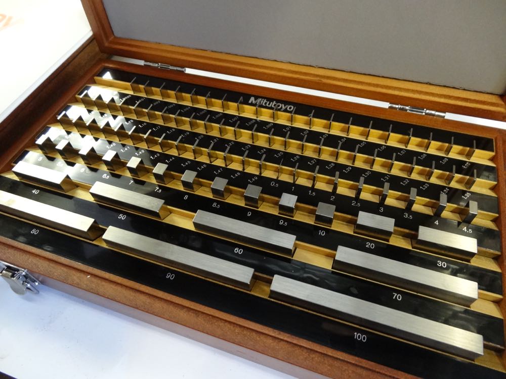
Slip gauges were first developed by Johnson, and sometimes also called as ‘Johnson Gauge Blocks’. These are rectangular blocks of steel having a cross-section of about 32 mm x 9 mm.
Slip gauges are the universally accepted ‘standard of length’ in industries. These are the simplest possible means of measuring linear dimensions very accurately.
ADVERTISEMENTS:
Need of Slip Gauges:
For tool-room and other precision work, the ordinary methods of measurement are not always accurate. Micrometer and verniers calliper can be used to check tolerance fine within 0.002 to 0.02 mm, but for fine tolerance they are not effective. Thus there is a need of instrument which can measure fine tolerance limit.
The means to do so are ‘slip gauges’. They can be used to measure tolerances in the range of 0.001 to 0.0005 mm very accurately.
Grades of Accuracy of Slip Gauges:
Slip gauges are made in five grades of accuracy. Calibration grade, grade 00, grade 0, grade I, and grade II, in the decreasing order of accuracy.
ADVERTISEMENTS:
Grade 0, grade I, grade II are used for general workshop purpose and are known as working gauge blocks, whereas, calibration grade (master gauge blocks) and grade 00 (Inspection gauge blocks) are used only for checking other types of blocks.
(i) Calibration Grade:
This is special grade and is used for experimental work, research work and for measurement and inspection of other gauges (grades).
(ii) Grade 00:
ADVERTISEMENTS:
This is also termed as inspection gauge block. This is used for highest precision work such as measuring Grade I and II.
(iii) Grade 0:
This is used for tool room or machine shop inspection.
(iv) Grade I:
ADVERTISEMENTS:
This is used for more precise work such as setting up sine bars, checking gap gauges, measurement of components, tools etc.
(v) Grade II:
This is used in workshop for rough checks, for ordinary inspection work, for setting up machine tools, and for measurement where production tolerances are relatively wide.
Slip Gauges Sets:
ADVERTISEMENTS:
Gauge blocks are available in sets with steps with steps of 10, 1, 0.1, 0.01 and 0.001 mm. on small size blocks, the size is marked on the measuring face, and large blocks are marked on a side surface.
The sets are available in ‘Metric’ and ‘English’ units. Letter ‘E’ is used for inch units (English units) and
Letter “M’ is used for mm units (Metric units). The number of pieces in a set is given by the number followed by letter E or M.
For Example, E 81 refers to a set whose blocks are in inch unit and 81 in number. Similarly M 45 refers to a set whose blocks are in mm units and are 45 in number.
Some available Metric (mm) and English (inches) sets are:
M122, M106, M87, M 50, M 33, M27 and E 81, E 49, E 41, E 35, E 28

Protective Slips:
Apart from these above, two extra gauges of 2.5 mm each are also supplied as protective slips. The purposes of protective slips are to prolong the life of slip gauges. These are often made of the same material as the rest of the sets or sometimes they may be made from tungsten carbide, which is a wear resistant material.
Protective slips identified by letter ‘P’ marked on one face. These are placed at each end of the assembled blocks, to ensure that any wear or damage is confined to these two blocks.
The use of protector blocks at each end of slip pile will extend the accuracy and hence the useful life of the gauge block, but there is disadvantage associated to use of protective slips that the minimum number of gauge blocks in a slip pile often increases as it obvious from the following example:
Example:
ADVERTISEMENTS:
Building a size of 43.716 using a pair of 2.5 mm protector blocks and M45 set.

Example:
Building a size of 43.716 mm using M45 set.
ADVERTISEMENTS:


Example:
Building a size of 55.87 mm using M 45 set.

Example:
To build up dimensions of 30.87 mm and 23.258 mm using set M110 and M45 pieces, respectively.

Wringing Process:
If two blocks are twisted together under certain pressure, it will be found that due to molecular attraction and atmospheric pressure they will adhere to each other quite firmly. This process is known as wringing. This Process is very useful to produce a required size by assemble several gauge blocks.
Before wringing of blocks; wipe them clean using a cloth, chamois leather, or a cleansing tissue. Vaseline, grease or dust should be removed by petroleum.
Start wringing with the largest sizes first. Place two faces together at right angles as shown in figure 1.8 (b) and (c), and, with pressure, twist through 90°. This action should be smooth and with constant pressure.
When the largest gauges have been assembled, follow same process with the others in order of decreasing size of blocks.

Method of Assembly:
To produce an assembly of required dimensions, begin with the smallest increment of size and subtract this from the required dimension.
Eliminate the next smallest number in the same way, and repeat this procedure until the assembly is complete. This process will give the minimum number of gauge blocks necessary to build up the given dimension.
Example:
To build up a assembly of 59.361 mm by using set M86.

Accuracy of Gauge Blocks:
The accuracy of gauge blokes is affected by temperature changes. They are accurate within a temperature of 20°C and humidity controlled atmosphere. Their accuracy should be checked time-to-time against any warn out or deformation in the blocks.
To do so, in industries, a set of gauge blocks are available as a reference set, to check the other working sets.
Manufacturing of Slip Gauges:
(Material) Most of the slip gauges are produced from high grade steel, hardened and stabilized by heat treatment process to give a high degree of dimensional stability. Slip gauges can be made from tool steel, chrome plate steel.
Stainless steel, chrome carbide, tungsten carbide etc. Tungsten carbide is an extremely hard, wear resistant, and most expensive material than steel. Sometimes chrome plating is also used to improves the corrosion resistance.
Addition of chrome plates leads to the tendency of Flake-off, especially at the edges. Hence they are disliked by experienced workers.
(Method) Following steps gives a brief of method of manufacturing of slip gauges:
1. The high grade steel gauge blanks are taken with appropriate size.
2. They are subjected to hardened and rough grinding process.
3. Then they are subjected to a cyclic low temperature heat treatment, to provide stability of dimensions and to relieve the internal stress.
4. A batch of 8 blanks of similar nominal size is mounted on eight Co-planner Faces of a magnetic chuck.
5. Their one set of Faces is lapped truly flat by lapping process.
6. By changing the lapped faces on magnetic chuck, opposite Faces also lapped truly flat.
7. Now, the required Parallelism and equality of size is achieved by interchanging four of the eight gauges as shown in figure 1.8 (e). They are interchanged diagonally and turned end for end. Thus any errors in Parallelism are equalized.
8. Now, to determine whether the gauges are the required size they are removed from the chuck, wrong together in combination, and their aggregate size compared with an appropriate size master in a suitable comparator. A magnification of 8 is obtained in this calibration since, as each of the 8 gauges must be identical in size, the difference between combination and master may be divided by eight and this difference is distributed to each gauge.
9. If necessary, individual block can be mounted on chuck to bring their individual lengths within required accuracy.
Uses of Slip Gauges:
Slip gauges are important means of measurement in industries and laboratories.
Their uses are:
1. They universally accepted as a “Standard of length”.
2. They used for direct precise measurement where accuracy of work piece being measure is high.
3. They used with high-magnification comparators, to establish the size of the gauge blocks.
4. They are used for checking the accuracy of measuring instruments.
5. They are used to setting up a comparator to specific dimension.
6. They are used to check a batch of components quickly and accurately.
Care of Slip Gauges:
Since the initial cost of slip gauges in high, so to maintain their accuracy, they require great care.
Following points should be kept in mind regarding the care of slip gauges:
1. When not in use, the slip gauges should be kept in their respective positions in the gauge box.
2. Before wringing the blocks together, ensure that their faces are perfectly clean.
3. Measuring faces should not be fingered.
4. Gauges should not be wrong together over an open gauge box, due to the possibility of accidently drop of any gauge on several gauges placed in the box and could be damaged.
5. Gauges should not be wrung together for a long time.
6. After use, does not break the pile but slide one gauge over the other to separate them.
7. After use, a thin layer of good quality grease should be applied on their faces, before they are kept in their case.
8. As far as possible, slip gauges should be used in air-conditioned rooms, free from dust and maintained constant temperature.
9. During the use, their working faces should never be placed on the surface plate etc.
10. Check accuracy at appropriate intervals.
11. Use minimum number of gauges for a combination.
12. Wring together in correct manner.
13. Use 2.5mm protector slips whenever possible.
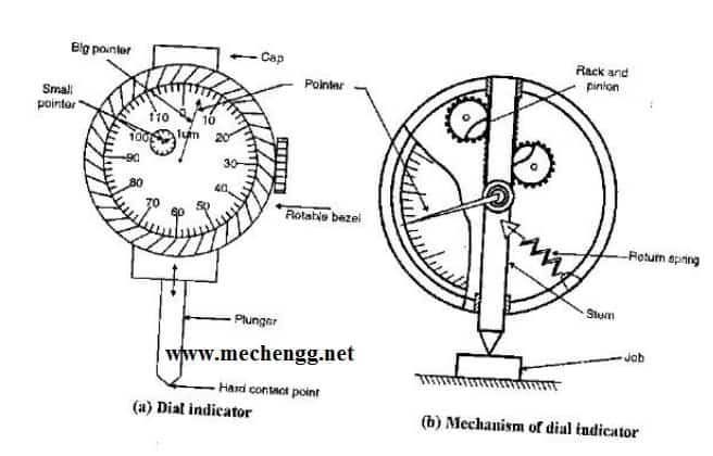
DIAL INDICATOR
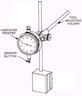
It operates on the principle, that a very slight upward pressure on the spindle at the contact point is multiplied through a system of gears and levers. It is indicated on the face of the dial by a dial finger. Dial indicators basically consists of a body with a round graduated dial and a contact point connected with a spiral or gear train so that hand on the dial face indicates the amount of movement of the contact point. They are designed for use on a wide range of standard measuring devices such as dial box gauges, portal dial, hand gauges, dial depth gauges, diameter gauges and dial indicator snap gauge.
Corresponds to a spindle movement of 1 mm. The movement mechanism of the instrument is housed in a metal case for it’s protection. The large dial scale is graduated into 100 divisions. The indicator is set to zero by the use of slip gauges representing the basic size of part.
Requirements of Good Dial Indicator:
1. It should give trouble free and dependable readings over a long period.
2. The pressure required on measuring head to obtain zero reading must remain constant over the whole range.
3. The pointer should indicate the direction of movement of the measuring plunger.
4. The accuracy of the readings should be within close limits of the various sizes and ranges
5. The movement of the measuring plunger should be in either direction without affecting the accuracy.
6. The pointer movement should be damped, so that it will not oscillate when the readings are being taken.
Applications:
1. Comparing two heights or distances between narrow limits.
2. To determine the errors in geometrical form such as ovality, roundness and taper.
3. For taking accurate measurement of deformation such as intension and compression.
4. To determine positional errors of surfaces such as parallelism, squareness and alignment.
5. To check the alignment of lathe centers by using suitable accurate bar between the centers.
6. To check trueness of milling machine arbours and to check the parallelism of shaper arm with table surface or vice.
ANGLE MEASUREMENTS
There are a wide variety of geometries that are measured in angular units. These varieties include angular separation of bounding planes, digression from a basic direction, angular spacing conditions related to a circle, etc. Because of these diverse geometrical forms, different types of methods, equipment and instruments are available to measure angles in common angular units of degree, minute and second.
Several factors come into the role in the selection of appropriate angular measuring instrument. These factors may be the size, general shape of the part, the location and angular accessibility of the feature to be measured, expected a range of accuracy, etc.
As in linear measurement, they can be categorized into two groups. The first one is standard line instrument. It includes divided scales like protractors, Bevel Protractors. The second category of angular measuring instruments is called face standard instruments. Sine bars and angle gauges fall in this group.
Protractors:
The protractor is the simplest instrument for measuring angles between two faces. It consists of two arms and an engraved circular scale. The two arms can be set along the faces between which the angle is to be measured. The body of the instrument is extended to form one of the arms. A simple protractor consists of a blade that pivots about a semicircular head that is graduated in angular units (e.g., degrees, radians). To use, the blade is rotated to a position corresponding to some part angle to be measured and the angle is read off the angular scale.
Bevel Protractor:
Bevel Protractor is an angular measuring instrument capable of measuring angles to within 5 min. Bevel Protractor consists of a base to which a vernier scale is fixed. A protractor dial is mounted on the circular section of the base. The protractor dial is marked in degrees with every tenth degree numbered. The sliding blade is fitted into the dial; it may be extended to either sides and set at any angle to the base. The blade and the dial are rotated together as a unit. Fine adjustment is obtained with a small knurled headed pinion that, when turned, engages with a gear attached to the blade mount. The protractor dial may be locked in any position using the dial clamp nut.
Measurement in a bevel protractor instrument is made either by embracing the two bounding elements of the angle or by extraneous referencing. The vernier protractor is used to measure an angle greater than 90° but less than 180°. An acute angle attachment is fastened to the vernier protractor to measure angles less than 90°. The main scale is divided into two arcs of 180°. Each arc is divided into two quadrants of 90° and has graduation from 0° to 90° to the left and right of the zero line, with every tenth degree numbered. The vernier scale is divided into 12 spaces on each side of its zero (total 24). The spacing in the vernier scale is made in such a way that least count of it corresponds to 1 /12th of a degree, which is equal to 5′.
If the zero on the vernier scale coincides with a line on the main scale, the number of vernier graduations beyond the zero need to be multiplied by 5 and added to the number of full degrees indicated on the vernier protractor dial.
Below image shows a diagram of a bevel protractor.
Sine Bars:
High precision in angular measurements can be made using a sine bar instrument, illustrated in Figure 4. One possible setup consists of a flat steel straight edge (the sine bar), and two precision rolls set a known distance apart on the bar. The straight edge is aligned with the part angle to be measured, and gauge blocks or other accurate linear measurements are made to determine height. The measurement using sine bar is carried out on a surface plate to achieve most accurate results. This height ‘H’ and the length ‘L’ of the sine bar between rolls are used to calculate the angle ‘A’ using the formula
Angle Slip Gauge

"Mikronix" introducing Angle Slip Gauges as per IS : 6231 - 1971 , designed for the inspection and calibration of angle, tapers, indexing plates, rotary scales, clinometers, dividing heads, rotary tables etc.
Set A
|
|
Set B
|
|
Note: Any angle beyond 81° in the case of Set A and 90° in the case of Set B, can be obtained suitably using the precision square block of steel provided along with each set. The above sets along with the square block enable to be built up to 6 seconds, that is to within ±3 seconds of the required angle.
Slip Gauge Accessories are available in two sets 17 - pieces and 7- piecesCOMPARATORS Chapter Outline Comparators
– Introduction to comparators
– Characteristics
– Uses of Comparators
– Classification of comparators
– Mechanical comparators
• Dial indicator
• Johnson Mikrokator
• Sigma comparators
Optical comparators
– Principles,
– Zeiss ultra optimeter,
Electric and electronic comparators principles,
– LVDT,
Pneumatic comparators,
– Back pressure gauges,
– Solex comparators.
Type # 1. Mechanical Comparators:
A mechanical comparator employs mechanical means to get the magnification for example, lever, gear system etc. Its manufacturing requires high degree of skile and accuracy. The magnification of mechanical comparator ranges from 250 to 1000.
Different types of mechanical comparators are:
ADVERTISEMENTS:
1. Dial Indicators.
2. Lever Comparators.
3. Sigma Comparators.
4. Johanson Mikro kator.
ADVERTISEMENTS:
5. Read type Comparators.
1. Dial Indicators:
A dial indicator is simplest type of mechanical comparator. It is very versatile and sensitive instrument. It uses gear system together with a rack and pinion.
The Principle of Operation:
“A very slight upward pressure on the spindle at the contact plunger is magnified through a system of gears and levers and is indicated on dial by pointer and scale.”
ADVERTISEMENTS:
The dial has a scale division value of 0.01mm usually. The whole arrangement is housed in a metal case for its protection. Dial is graduated into 100 divisions.
A suitable spring gives constant plunger pressure, while hair spring may be employed to eliminate play or hacklash.

Dial gauges are usually available having dial graduation of 0.01 mm or even 0.02 mm. Some sensitive types of dial gauge have graduation of 0.002 mm.
ADVERTISEMENTS:
Uses:
The dial indicator is used for:
(i) Determining the error in geometrical form, say, taper, roundness, ovality etc.
(ii) Determining the errors is surfaces, say alignment, Parallelism, squareness etc.
ADVERTISEMENTS:
(iii) Used for comparison of two heights or distance within small limits
(iv) Used for compression and tension testing of materials.
Practical Application:
(i) To check the trueness of milling machine arbers.
(ii) To check the parallelism of shape machine ram with surface.
(iii) To check the alignment of lathe machine centers by using a bar between centers.
2. Lever Comparators:
A Lever Comparator is a simple and important type of mechanical comparator. It employs a ‘lever’ for obtain magnification of movement or displacement.

Principle of Operation:
The Principle of operation of lever type comparator is shown in Fig. 1.11, First of all, a pile of slip gauges of standard dimension is placed to anvil surface, below the plunger and the pointer set to zero.
Now, place the component to be measured on the anvil surface below plunger by removing the pile of slip gauges.
If there is any difference in size, the plunger moves up and down. These plunger movements are magnified, by lever and deflect the pointer on a graduated scale.
A compression spring limits the measuring pressure. The magnification achieved depends upon the length of lever both side of the pivot.
The magnification is given by:
ADVERTISEMENTS:

3. Sigma Comparator:
Sigma Comparator is a most popular, British-designed, British manufactured mechanical Comparator. This is available in various choices of scale ranges.
The magnification of sigma comparators usually of 1000:1, Means a plunger movement of 0.002 mm will result in movement of pointer by 2mm on calibrated scale.
ADVERTISEMENTS:
Construction:
A typical Sigma Comparator is shown in Figure 1.12.
Different parts of this comparator are:
(i) Base:
It consists of a cast iron base, for mounting all the parts of comparator along with the work component to be measure.
(ii) Column:
It consists of a threaded vertical column, mounted on the base to hold the measuring head.
(iii) Measuring Head:
It consists of a Measuring Head, mounted on the vertical threaded column. Measuring Head provided with pointer, scale, tolerance pointer setting control knobs, trigger, measuring contract tip.
(iv) Work Table:
A work table is provided at bottom of the column, below the measuring head, having perfectly planed horizontal surface for placement of component to be measure or check.
(v) Vertical Spindle:
Measuring head carries a vertical spindle which is mounted on two flat steel springs. The spindle works inside fixed guides attached to the back plate of the head. This arrangement provides a frictionless movement of the spindle. The springs provide a resistant pressure on the spindle.
(vi) Measuring Contact Tip:
A measuring contact tip is fitted with a shank and shank is fitted to spindle.
(vii) A Stop:
A stop is suitably provided in the assembly to restrict the spindle movement at lowest position of the scale.
(viii) A Trigger:
A trigger lever projects outside the measuring head. This is incorporate in the mechanism for elevating the measuring contact when required.
Procedure:
For checking the size of a component, the dial pointer is first set to zero reading by means of a combination of slip gauges of standard dimensions, resting on the work table. This combination of slip gauges then replaced by the work piece and difference in dimensions is noted from the movement of a pointer on graduated scale.
Special Features:
(i) The pointer is actuated by downward movement of the plunger, thus eliminating the possibility of damage to the mechanism from excessive upward pressure on the plunger.
(ii) Both the contact tip and worktable are Interchangeable, according to the shape and size of the component to be checked.
(iii) These comparators are available in different vertical capacities from 150 to 600mm; means components up to 600mm in height can be checked.
Magnification Range:
The magnifications achieved by Sigma Comparators are in the range of 1000 to 2000. Means a plunger movement of 0.002 mm can be magnify up to deflection of pointer of 2mm. Most sensitive model is available which can detect the plunger movement of 0.0001mm (0. 1 um).
Advantages of Mechanical Comparators:
(i) Low Cost:
These instruments are usually cheaper than other types of comparators.
(ii) Need not Electricity:
These instruments do not required any external source of power supply or air as in the case of pneumatic or electrical comparators. Hence outside sources do not affect the accuracy of the comparator.
(iii) Linear Scale:
These installments usually have linear scale, which is easy to read.
(iv) Easy to Handle:
These installments are usually robust and compact so easy to handle.
(v) Suitable to Workshop:
These instruments are portable and can be issued from store keeper in workshop.
Disadvantages of Mechanical Comparators:
(i) Friction is More:
These instruments usually have many moving linkages as compared to the other type of comparators. Due to more moving parts, the friction is more.
(ii) Inertia is More:
These instruments usually have more inertia. Hence these instruments are very sensitive to vibrations.
(iii) Accuracy is Less:
These instruments usually have low accuracy due to more friction and high inertia.
(iv) Wear, Play, Backlesh:
Any wear, play, backlesh or dimensional inaccuracy in the device used will also be magnified. This increases the error in the measurement.
(v) Range is Limited:
These instruments usually have limited range of measurement, as the pointer moves over a fixed scale.
(vi) Parallax Error:
These instruments usually affected with error due to parallax as the pointer moves over a fixed scale.
Type # 2. Electrical Comparators:
An Electrical comparator employs electrical means to get the magnification. In this comparator the movement of the measuring contact plunger is converted into an electrical signal.
The electrical signal is recorded by an instrument which can be calibrated in terms of plunger movement.

Construction:
An electrical comparator consists of four basic units.
(i) Measuring Probe (Plunger):
This is in direct contact of the component being checked.
(ii) Amplifier and Indicating Unit:
Amplifier boost up the electrical signals obtained and gives to indicating unit. Indicating unit indicates the variation of dimensions if any by movement of pointer on a calibrated scale.
(iii) Power Unit:
Power unit gives the power to the wheat-stone bridge to balance it while setting the pointer to zero with respected to standard component.
(iv) Base and Standard Unit:
These provide hold and support to all the other units. Other than four basic units, a spring is provided to control the contact pressure. A thin flexible steel strip also provided as shown in Figure. 1.13 (a).
Working Principle:
The principle of operation of an electrical comparator is shown in Fig. 1.13 (a) an armature supported on thin flexible steel strip is suspended between two coils C and C. When the distance of the armature from two coils is equal, the Wheatstone bridge is balanced and no current flows through the galvanometer.
Little movement of the measuring plunger unbalances the bridge resulting in the flow of current through the galvanometer. Galvanometer scale is calibrated to give the movements of the plunger.
Magnification:
Electrical comparators are available to read up to 0.0001mm with magnification ranging between 1100-18,000. Some most sensitive electrical comparators available with magnification of 40,000 or higher.
Special Features:
These comparators could also be supplied with indicators, which would give out a signal if the component being checked lies below or above the standard dimensions. The signal from the indicator may either be coloured lamps or a buzzer sound.
This principle is known as “Visual gauging Head”. Such, instruments do not provide any difference in dimension but gives only a Visual Indication.
Advantage of Electrical Comparators:
(i) High Degree of Reliability:
Since mechanical comparators actuated by gears, levers, rack and pinion etc.; all of these are subjected to wear and friction and tanee affect the accuracy and useful life of the instrument.
On the other hand, electrical comparators possess a minimum number of moving parts, thus we can expect a high degree of reliability from these instruments.
(ii) Remote Measurement:
Indicating instrument can be remote from the measuring unit.
(iii) High Magnification:
Due to reduced friction, wear, and with minimum moving parts, these comparators have a high magnification.
(iv) Not Sensitive to Vibrations:
The mechanism carrying pointer is light and not sensitive to vibration.
Disadvantages of Electrical Comparators:
(i) High Cost:
These instruments usually more expensive than the mechanical comparators.
(ii) External Power Source:
These instruments require an external agency to operate i.e., a.c. electric supply Thus the fluctuation in voltage or frequency may affect the accuracy of measurement.
(iii) Heating of Coils:
Heating of coils in the system may cause to alter the calibration.
(iv) Fized Scale:
If only a fixed scale in used with a moving pointer then with high magnifications, a small range is obtained.
Type # 3. Optical Comparators:
There is no pure optical comparator but large magnification is obtained by use of optical principle in optical comparators.
A mechanical instrument also contributes quite a lot for the overall magnification. Hence sometimes it is referred as ‘Mech-optical comparator’.
Magnification in case of optical comparators is obtained with the help of light beams which has an advantage of being straight and weightless. Optical comparators have their own built in light source.
Principle of Working:
The optical principle adopted in the optical comparators is ‘optical lever’ and is shown in Fig. 1.14.
If a ray of light AC strikes a mirror, it is reflected as ray CO such that:
∠ACN =∠NCO

Now, if the mirror is tilted through an angle a, the reflected ray of light has moved through an angle of 2a.
In optical comparators, the minor is tilted by the measuring plunger movement and the movement of reflected light is recorded as an image on a screen.
Fig. 1.15 shows the working principle of an optical-mechanical comparator in which both mechanical and optical levers are used.

Magnification:
The magnification of optical comparator is defined as “the ratio between distance moved by the indicating pointer (beam) and the displacement of plunger”.

The Magnification of optical comparators is usually 1000:1, with measuring range of plus and minus 0.075 mm.
Advantages of Optical Comparators:
1. High Accuracy:
These comparators have usually a few moving linkage and hence are not subjected to wear tear, and much friction and give high accuracy.
2. High Range:
These comparators have a scale which can be made past a datum line and thus have high range.
3. High Magnification:
The Magnification is usually high.
4. No Inertia:
A beam of light is used for magnification which has no inertia.
5. Parallex Eerror:
Parallex error is not there.
Disadvantages of Optical Comparators:
1. Costly:
Optical comparators are costly than other types like mechanical and electrical comparators.
2. Size:
The size of the optical comparator is large.
3. Need Source of Light:
Optical comparators require the electric supply to operate the source of light.
4. Heating of Instrument:
Heating from source of light affects the accuracy of the measurement.
5. Need of Dark Room:
Dark room is required to take readings easily and properly.
6. Reading not Convenient:
Taking readings continuously through the eye-piece in not convenient.
Type # 4. Pneumatic Comparators:
Pneumatic Comparators uses air as a means of magnification in metrology. This was originally developed by the Solex Company in France for the calibration of carburetors.
The first application was the checking of the bores of motor-car cylinder blocks. Now it is almost used in production shop for this purpose.

Working Principle:
The Pneumatic Comparator is based on Bernoulli’s theory. The principle of working of a Pneumatic comparator is shown in figure 1.16. Air at a low (1,5kg./cm2) but constant pressure, ps, is supplied through a small jet ‘c’ into an intermediate chamber and then pass through a second orifice gauging jet ‘G’ to atmosphere.
The component whose dimensions to be checked is placed below the gauging jet with some air gap as shown on Fig. 1.16. The amount of air escaping through gap between work piece ‘p’ and gauging jet ‘G’ will depend upon the gap h. The gap h will affect the intermediate pressure recorded by the manometer “M”.
If the gap ‘h’ is large, pressure recorded would be small. On the other hand if the gap ‘h’ is small, pressure would be higher.
The gap ‘h’ initially set with the help of known standard usually slips gauges. The component whose dimensions to be checked is placed by removing the slip gauges.
If the component has variation in size than the gap ‘h’ will increased or decreased. This will cause to change in intermediate pressure, and will change in the manometer reading. The manometer is calibrated directly to read linear scale.
Magnification:
A high order of magnification is possible because no physical contact is made to the part being checked. The Magnification possible with this type of comparator is as high as 30,000: 1, but are usually about 10,000: 1.
Uses and Applications:
Pneumatic Comparators can be applied to internal and external diameter measurements, thickness measurements. They can also be applied to check the concentricity of angular parts, depth of blind holes, parallelism flatness, hole centre distance, etc. Fig. 1.17 shows some applications of pneumatic comparators.


Advantages of Pneumatic Comparators:
1. High Accuracy:
Since the part to be checked does not comes in contact of measuring probe and hence no wear takes place on the gauging probe. Also this incorporates very less number of moving parts thus less friction and less inertia will leads to high accuracy.
2. Higher Magnification:
A high as 30,000:1 magnification can be achieved with pneumatic comparators.
3. Cleaning of Dust:
Jet of air helps in cleaning the dust, if any, from the component being measured.
4. Checking of Surface Positions:
Pneumatic comparators are the best means for determining the ovality, straightness, flatness, squareness, roundness, taperness and circular bores.
Disadvantages of Pneumatic Comparators:
1. Need of Auxiliary Equipment’s:
Pneumatic comparators require auxiliary equipment for their proper functioning, like accurate pressure regulator.
2. Non-Uniform Scale:
The scale of Pneumatic Comparators is generally not uniform.
3. Not Portable:
The whole apparatus is not portable.
4. Effect of Temp:
Humidity and surface roughness: Pneumatic Comparators are sensitive to temperature and humidity changes. Their accuracy will also affected by the surface roughness of component being checked.
Type # 5. Fluid Displacement Comparators:
Fluid displacement comparators work on the principle of displacement of fluid. These comparators find only limited applications in metrology.
Working Principle:
The operation of these comparators depends upon the displacement of fluid from the large section of the comparator to the relatively smaller section of the comparator with displacement of the feeler or plunger.
The component to be checked is placed below the measuring plunger. If any deviation in size of the component then the diaphragm deflects a small quantity of fluid. This small quantity of deflected fluid will cause to raise fluid in capillary tube. A scale is available with the capillary tube with indicates the limit points of fluid raised or lowered. A fluid displacement comparator is shown in Fig. 1.18.

Magnification:
Magnification of fluid displacement comparators is approximately given by:
MEASUREMENT OF SURFACE ROUGHNESS
Surface Roughness By Comparison Chart


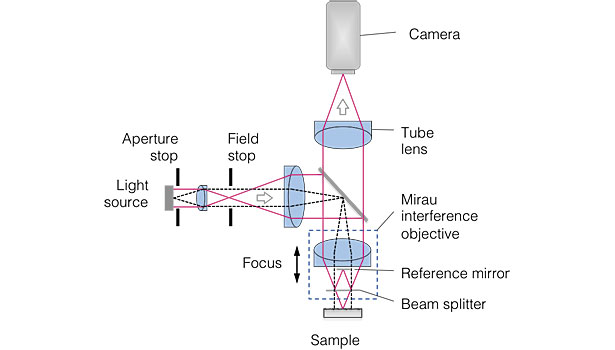
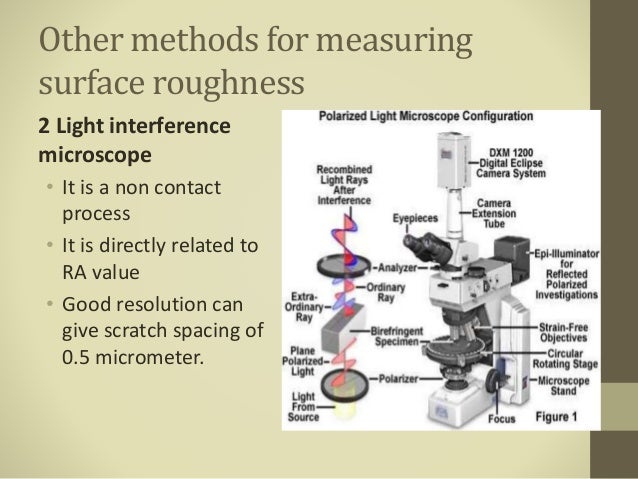
Surface roughness measurements were performed on a glass-ceramic disk substrate by stylus profiler (SP), atomic force microscope ( AFM) and non-contact optical profiler (NOP). Results of surface measurements are presented and the differences between SP, AFM and NOP roughness measurements are discussed. The effects of stylus size, scan size and sampling interval on roughness parameters are investigated. The methodology of choosing the scan size and sampling interval is suggested. APM is concluded to be the most suitable surface measuring instrument for roughness measurement on the glass-ceramic substrate. If SP is used to make the measurement, the tip radius should be in the order of 0.2 pm. However, localized damage to the test surface may occur owing to high contact stress. NOP using an objective magnification of 40 or lower is not recommended because the glass-ceramic substrate contains submicron roughness.
BY TREASURE INSTRUMENT AND INTERFEROMETER
AUTOCOLLIMATORS
An autocollimator is an optical instruments for non-contact measurement of angles. They are typically used to align components and measure deflections in optical or mechanical systems. An autocollimator works by projecting an image onto a target mirror and measuring the deflection of the returned image against a scale, either visually or by means of an electronic detector. A visual autocollimator can measure angles as small as 1 arc-second (4.85 micro-radians), while an electronic autocollimator can have up to 100 times more resolution.
Visual autocollimators are often used for aligning laser rod ends and checking the face parallelism of optical windows and wedges. Electronic and digital autocollimators are used as angle measurement standards, for monitoring angular movement over long periods of time and for checking angular position repeatability in mechanical systems. Servo autocollimators are specialized compact forms of electronic autocollimators that are used in high-speed servo-feedback loops for stable-platform applications. An electronic autocollimator is typically calibrated to read the actual mirror angle.
COLLIMATOR
A collimator is a device which narrows a beam of particles or waves. To narrow can mean either to cause the directions of motion to become more aligned in a specific direction (i.e., make collimated light or parallel rays), or to cause the spatial cross section of the beam to become smaller (beam limiting device).
TYPES
Optical collimators Xray , gamma ray , Neutron Collimator


Applications
The figure to the right illustrates how a Söller collimator is used in neutron and X-ray machines. The upper panel shows a situation where a collimator is not used, while the lower panel introduces a collimator. In both panels the source of radiation is to the right, and the image is recorded on the gray plate at the left of the panels.
Without a collimator, rays from all directions will be recorded; for example, a ray that has passed through the top of the specimen (to the right of the diagram) but happens to be travelling in a downwards direction may be recorded at the bottom of the plate. The resultant image will be so blurred and indistinct as to be useless.
Surface Roughness Measurement by Scanning Electron Microscope

Shadow Graph Profile Projector
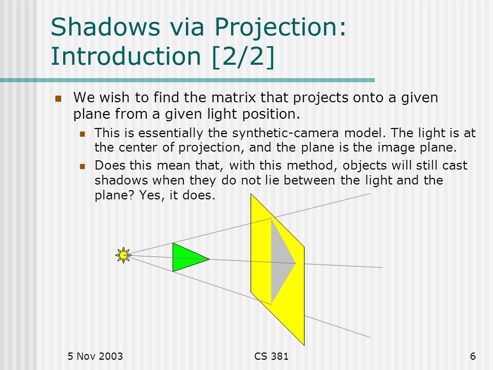
The performance of an electron gun is evaluated in terms of the gun brightness. The brightness of an electron gun is typically measured by dividing the angular current density by the virtual source area. An electron gun brightness measurement system was constructed without an electron lens. The system consists of movable apertures (∅ 30, 50, 100, 200 ), a Faraday cup, and a phosphor screen. The Faraday cup is employed to measure the angular current density. The electron beam passes through an aperture and its shade is projected onto the phosphor screen. The virtual source position is determined by measuring the displacement of the aperture shade made by the movement of the aperture. The blurring width of the edge of the shadow on the screen is measured by a charged-coupled device camera to calculate the virtual source size. Brightness values of a tungsten filament electron gun were obtained and compared to reported values
ACKNOWLEDGMENTS
We would like to acknowledge the financial support from the R & D Convergence Program of NST (National Research Council of Science and Technology) of the Republic of Korea (Grant No. CAP-14-3-KRISS). This research was also supported by Korea Basic Science Institute Grant No. (D36612).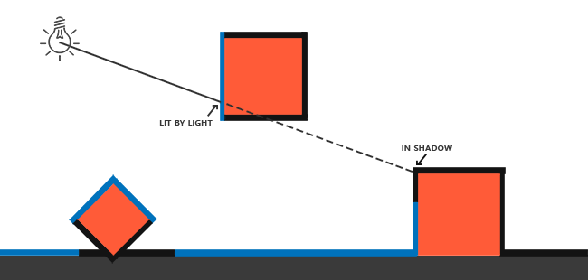
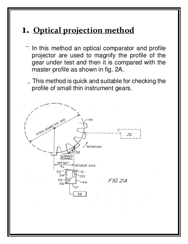
PROFILE PROJECTION
In Image Processing, projection profile refers to projection of sum of hits/positives along an axis from bi-dimensional image. Projection profile method is majorly used for segmentation of text objects present inside text documents.
Solution:
Note: Projection profile is calculated for a thresholded image or binarized image where a thresholded image is a grayscale image with pixel values as 0 or 255. Image pixels are replaced by 1 and 0 for pixel values 0 and 255 respectively.
Projection profile is calculated separately for different axis. Projection profile along vertical axis is called Vertical Projection profile. Vertical projection profile is calculated for every column as sum of all row pixel values inside the column. Horizontal Projection profile is the projection profile of a image along horizontal axis. Horizontal Projection profile is calculated for every row as sum of all column pixel values inside the row.


----------------------------------------------------------The END----------------------------------------------
Share and Subscribe ..........................Thank you
Your blog is very useful and provides tremendous facts. Keep up the good work. Optical Polishing and Thin Film Coating .
ReplyDelete