Dial Indicator | Dial Gauge | Types Of Dial Indicators | Working Principle
The Dial indicator is a mechanical mean, having gears and pinions or levers for magnification system. They can responses to linear measurement even when they are too small.
The Dial Indicators can be used as Comparotors
Basically, comparators are the precession measuring instruments used to compare the workpiece measurements with the standard measurements.
When this Dial Indicator is used in any measuring equipment for comparison purpose then these equipment are called Dial Gauges.
A Dial Indicator must be mounted on any other base/Equipment, otherwise, it will be useless.
The accuracy of the dial indicator is up to 0.001 mm are available.
Construction of Dial Indicators
There is a classification of dial indicators based on their dial shape. They are sector shape Dial Indicator and Circular shape Dial Indicator.
But sector type is a quite limited range, so this sector type Dial Indicator is used for extremely accurate measurements.
The circular type of Dial Indicators can be classified into two types based on their Mechanisms
Gear and Pinion type Dial Indicator
Lever Type Dial Indicator
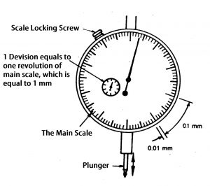
The Main Parts of Dial Indicator
Dial with the main scale
Indicator(Needle)
The plunger (spindle)
Mini dial (to represent the number of revolutions of the indicator.)
Locking screw
Magnification Mechanism(Lever/Gear and Pinion)
Working Principle of Gear and Pinion Mechanism in Dial indicator
The Principle of this gear and pinion is that the movement of the Plunger(spindle) will be multiplied thru the series of gears and pinions and indicated on the main scale on the dial by the indicator(Needle).
See the picture of the mechanism of the gear and pinion type of Dial Indicator.
The Plunger will be the one which is moving linearly with respect to the change in on the workpiece while taking measurements.
So the plunger will consist of a rack and it meshes with a pinion(P1) on the gear(G1)
This Gear (G1) will mesh with the series pinions and gears to multiply the movement to increase the accuracy of measurement.
The final Pinion (P3) is connected to the Indicator(Needle) this indicator will show the deflection on the main scale.
This is how the gear and pinion type dial indicator works.
Why is hairspring is provided in dial indicator?
Usually, the gears with the backlash are the concern. To avoid the backlash there is a Hairspring is provided at the gear. and there is another use of this hairspring, that is to control the movement of the plunger to regain its original position.
Working Principle of Lever Mechanism in Dial Indicator
The principle of the lever mechanism type of Dial Indicators is quite simple. The plunger and the indicator are connected by the levers as shown in figures.
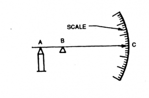
In simple Type lever mechanism the indicator is connected by a single lever (AC) is connect and pivoted at B point
Simple Lever Mechanism
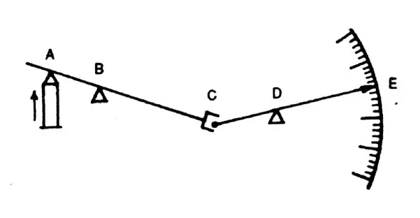
In the compound lever Mechanism, there are multiple levers connected. So this structure is difficult to construct because of the fork joints are shown in the figure at C
What is the linear measurement and Types of linear measuring instruments. There are a wide variety of geometries that are measured in angular units. These varieties include angular separation of bounding planes, digression from a basic direction, angular spacing conditions related to a circle, etc. Because of these diverse geometrical forms, different types of methods, equipment and instruments are available to measure angles in common angular units of degree, minute and second. Several factors come into the role in the selection of appropriate angular measuring instrument. These factors may be the size, general shape of the part, the location and angular accessibility of the feature to be measured, expected a range of accuracy, etc. As in linear measurement, they can be categorized into two groups. The first one is standard line instrument. It includes divided scales like protractors, Bevel Protractors. The second category of angular measuring instrum...
RRB JE Syllabus for 2nd Stage CBT The Questions will be of objective type with multiple choices and are likely to include questions pertaining to General Awareness, Physics and Chemistry, Basics of Computers and Applications, Basics of Environment and Pollution Control and Technical abilities for the post. The syllabus for General Awareness, Physics and Chemistry, Basics of Computers and Applications, Basics of Environment and Pollution Control is common for all notified posts: a) General Awareness : Knowledge of Current affairs, Indian geography, culture and history of India including freedom struggle, Indian Polity and constitution, Indian Economy, Environmental issues concerning India and the World, Sports, General scientific and technological developments etc. b) Physics and Chemistry: Up to 10th standard CBSE syllabus. c) Basics of Computers and Applications: Architecture of Computers; input and Output devices; Storage devices, Networking, Operati...
Comments
Post a Comment